It is currently Sun Aug 16, 2026 2:14 pm

All times are UTC - 5 hours [ DST ]


Post new topic Reply to topic  [ 42 posts ]  Go to page Previous  1, 2, 3
Author Message
 Post subject: Re: Pyle-National
PostPosted: Tue Nov 27, 2012 4:43 pm 
User avatar

Joined: Sun Oct 10, 2004 11:30 am
Posts: 1263
Location: Eagan, MN
Okay...I can see that I was seriously in error in approving the registration of Pyle-National. The posts in question were pure marketing and had nothing to do with preservation and everything to do with promotion and marketing. They have, therefore, been deleted and the account deleted.

_________________
Doug Bailey, Webmaster http://www.steamlocomotive.info


Offline
 Profile  
 
 Post subject: Re: Pyle-National
PostPosted: Tue Nov 27, 2012 5:54 pm 

Joined: Thu Apr 14, 2005 9:34 pm
Posts: 2836
Location: Copenhagen, Denmark
If anyone, including those who have already commented, is interested in writing an instructional article on how to create computer files, and complete the process, for 3D part creation as described here, I know I would really enjoy the article and I bet others would too.

The information provided so far is just enough to interest me, but not enough for me to fully understand how to get it done myself. For example, I am still unclear what the various computer files mentioned so far are.

And if you need to start this in a new topic, great!

_________________
Steven Harrod
Lektor
Danmarks Tekniske Universitet


Offline
 Profile  
 
 Post subject: Re: Pyle-National
PostPosted: Tue Nov 27, 2012 7:53 pm 

Joined: Mon Feb 21, 2005 9:07 pm
Posts: 152
Location: The beautiful piney woods of East Texas
[quote="softwerkslex"]If anyone, including those who have already commented, is interested in writing an instructional article on how to create computer files, and complete the process, for 3D part creation as described here, I know I would really enjoy the article and I bet others would too.[/quote]

I'll allow my daughter, a CADD student at a technical high school, to chime in and answer a few questions:

When regarding creating computer files, do you mean creating 3D solid models or simply creating "production prints" if you will of the parts? Either way, there are many tutorials online for various solid modeling programs, although you would most likely have to purchase a home version of the software. I'm fluent in both SolidWorks and Autodesk Inventor programs, and have access to both at my home, school, and work. If someone wanted to create solid models of the parts, one could work from the original prints, or even reverse engineer the part if they had it available for that use. I hope this helps.


Offline
 Profile  
 
 Post subject: Re: Pyle-National
PostPosted: Tue Nov 27, 2012 8:15 pm 

Joined: Sun Aug 22, 2004 7:19 am
Posts: 6464
Location: southeastern USA
From old geezer with limited conceptual understanding:

1. You either draw with a CAD program or use a device that scans a 3 dimensional object to get your digital representation of the product. It uses a series of piled-up layers to represent each "slice" of the final project which is to be produced by layering each slice in production.
2. This file becomes a scalable basis for making the part bigger or smaller, crisper or sloppier, etc.......
3. A 3D printer extrudes a substance instead of ink, and the platen onto which it prints moves a set amount away from the printer head / extruder each pass (each layer). Your final product is a series of these extruded layers of substance (generally some form of thermoplasticy / resiny stuff if I understand correctly) all laid up and bonded together into a whole.

So, based on the more experienced advice in this thread, it sounds as if an extrudable substance for a 3D printer that can withstand steam locomotive stress and heat doesn't exist yet........but there's something that can be printed to make a pattern you can run down to the local aluminum foundry to have produced there. If it is a "lost" process, you just print whatever number of multiples you need.

I'm very interested to see how we can do intracately cored stuff like this......

dave

_________________
“God, the beautiful racket of it all: the sighing and hissing, the rattle and clack of the cars over the rails. These were the sounds that made America the greatest country on earth." Jonathan Evison


Offline
 Profile  
 
 Post subject: Re: Pyle-National
PostPosted: Tue Nov 27, 2012 9:31 pm 

Joined: Fri Mar 13, 2009 12:10 pm
Posts: 181
Location: TN
Dave wrote:
So, based on the more experienced advice in this thread, it sounds as if an extrudable substance for a 3D printer that can withstand steam locomotive stress and heat doesn't exist yet........but there's something that can be printed to make a pattern you can run down to the local aluminum foundry to have produced there. If it is a "lost" process, you just print whatever number of multiples you need.


I stated previously there's a company that can print stainless steel in suitable sizes for somewhat large parts (39.48 x 18.74 x 9.76 inch). Now the material properties of this type of stainless is not particularly comparable to most others, but it is a reasonable strength steel. This is an expensive approach, but may be cost effective to a one off part.

As far as making the 3D model in a 3D CAD software, the main industry standard programs average $1000-3000 depending on the package. Unless you're doing many of these parts, this might not be cost effective, though you can easily generate 2D drawings from such models, which is what I've ended up doing for a part drawing that I made for TVRM. There are companies that specialize in CAD services which can be an option. Another alternative being most engineering universities usually have licenses for these programs and may be looking for project for aspiring engineers. Could be worth a shot asking a local college for assistance in this, it could be a win-win situation for both parties. Some have 3D printers on campus, too (where I attend does, but are not of an adequate size or material for good patterns).

As well as there being many services for CAD, there are a rising number of services specifically for 3D printing (rapid prototyping or stereolithography being alternate nomenclature). Look around locally for some or there are many popping up on the internet which you can send files to print (Shapeways and i.materialise being the two most prominent).


Offline
 Profile  
 
 Post subject: Re: Pyle-National
PostPosted: Tue Nov 27, 2012 9:40 pm 

Joined: Mon Feb 21, 2005 9:07 pm
Posts: 152
Location: The beautiful piney woods of East Texas
Bill's daughter again over here:

I would be able to make a 3D model of the parts needed. Based on the pictures posted earlier in the thread, they didn't seem too complex or intricate. If anyone wants to use this as an option, feel free to contact my father through this and he'll send you along to contact me. As I stated before, I have access to the programs. Also, at my school, we have a 3D printer that prints in ABS plastic. While I know that this probably isn't likely to be able to withstand the temperatures of a steam engine, I still figured I should throw that out there.


Offline
 Profile  
 
 Post subject: Re: Pyle-National
PostPosted: Tue Nov 27, 2012 11:00 pm 

Joined: Sun May 20, 2007 10:27 am
Posts: 229
Location: New Haven Ct area
Dave wrote:
From old geezer with limited conceptual understanding:

1. You either draw with a CAD program or use a device that scans a 3 dimensional object to get your digital representation of the product. It uses a series of piled-up layers to represent each "slice" of the final project which is to be produced by layering each slice in production.
2. This file becomes a scalable basis for making the part bigger or smaller, crisper or sloppier, etc.......
3. A 3D printer extrudes a substance instead of ink, and the platen onto which it prints moves a set amount away from the printer head / extruder each pass (each layer). Your final product is a series of these extruded layers of substance (generally some form of thermoplasticy / resiny stuff if I understand correctly) all laid up and bonded together into a whole.

So, based on the more experienced advice in this thread, it sounds as if an extrudable substance for a 3D printer that can withstand steam locomotive stress and heat doesn't exist yet........but there's something that can be printed to make a pattern you can run down to the local aluminum foundry to have produced there. If it is a "lost" process, you just print whatever number of multiples you need.

I'm very interested to see how we can do intracately cored stuff like this......

dave


There are basically two ways you can print in 3D either you take a box of powder or polymer and selectively drop glue or use a laser to weld the particles and or resin together, then once you have worked on one layer, a big long bar comes across and deposits another little layer across the top. There are a few different processes under this umbrella (Stereo lithography, Selective laser sintering, 3d ink jet printing) Some of these techniques use a powder, some use a resin. The most interesting one for historic replication of large parts if you watched that youtube video is where your 3D printer actually goes and glues a bunch of particles of sand together. When you are all done you vacuum or shake out the areas where the sand is not glued together and those are your voids to pour the metal into. So you should with that process be able to build your cores right into the mold as part of the printing of the mold. If anyone needs a new set of cylinders for a locomotive this would be the way to go!

The other option is that you have what amounts to a CNC hot melt glue gun that goes around and around and shoots the material where needed. This is called Fused Deposition. In my experience the extruded hot melt glue type of machine is much cruder and makes ugly surface finishes that look unlike anything.

With the type where you are working with a big box of material that you are selectively gluing, or hardening the surface finishes can be very good and in cases where they get grainy it looks almost like a sand casting in some of the processes anyhow. So those are the basics as far as the systems printing directly to the metal those are using a pit of powdered steel and they use a laser to weld little bits together. The cost gets really high on that so generally it likely is best to just print the part or the mold. One great way to cut corners when printing molds is to just print the whole thing as a hollow shell so you aren't paying to print a lot of filler material. This you couldn't do when printing the final part yet works just fine for a mold. Then if you need the strength you back fill it with some sort of filler material it could be plaster of paris or something if it is just the pattern you are working on. If anyone is interested I heard back from a friend who should be going to the foundry shortly I could get you some photos and prices if you send me a PM. If anyone needs this and has a fun project I wouldn't mind volunteering to make some 3D part files if needed for the right group.

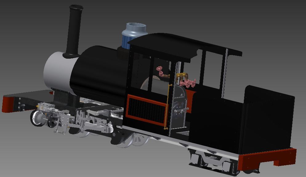
As far as programs to make the 3D part files I am using Autodesk Inventor on my computer here but there too the options that are coming out are changing really fast and the prices continue to fall. The nice thing a program like Inventor or Solidworks does is it allows you to model complete assemblies very well. I believe there are other free options I think Google may even have a 3D drawing program but I think where they fall short is when it comes to managing complete assemblies like a whole locomotive. Here's a picture of the 3.75" to the foot scale one I am building in Inventor;

Image


Offline
 Profile  
 
 Post subject: Re: Pyle-National
PostPosted: Wed Nov 28, 2012 2:51 pm 

Joined: Thu Apr 14, 2005 9:34 pm
Posts: 2836
Location: Copenhagen, Denmark
Question for example:

My son has a student edition of Autocad on his computer, and he is getting quite competent at making mechanical drawings. Apparently, with enough patience, any full time student may obtain Autocad for free.

What file format do I tell him to generate from Autocad? What design considerations should be observed in designing the part? Should care be taken to avoid certain shapes or sections? Are there certain Autocad features that support this task and make it easier?

How about a summary of vendors, and their offered materials? Pros and cons of various material choices available from this process (aluminum, bronze, stainless as mentioned)?

_________________
Steven Harrod
Lektor
Danmarks Tekniske Universitet


Offline
 Profile  
 
 Post subject: Re: Pyle-National
PostPosted: Wed Nov 28, 2012 3:47 pm 

Joined: Fri Mar 13, 2009 12:10 pm
Posts: 181
Location: TN
softwerkslex wrote:
Question for example:

My son has a student edition of Autocad on his computer, and he is getting quite competent at making mechanical drawings. Apparently, with enough patience, any full time student may obtain Autocad for free.

What file format do I tell him to generate from Autocad? What design considerations should be observed in designing the part? Should care be taken to avoid certain shapes or sections? Are there certain Autocad features that support this task and make it easier?

How about a summary of vendors, and their offered materials? Pros and cons of various material choices available from this process (aluminum, bronze, stainless as mentioned)?


AutoCAD is a primarily 2D CAD system, it has some 3D functionality, but limited compared to Autodesk Inventor (which he could get free as well) or Solidworks. Where I go, we use Solidworks, which to me is slightly superior to Inventor, but Dassault does not offer student licenses on the same level that Autodesk does. An STL file is the most common format I've seen used, but there are several others used for 3D printing.


Offline
 Profile  
 
 Post subject: Re: Pyle-National
PostPosted: Wed Nov 28, 2012 4:10 pm 

Joined: Sun Aug 22, 2004 7:58 am
Posts: 728
Quote:
AutoCAD is a primarily 2D CAD system, it has some 3D functionality, but limited compared to Autodesk Inventor (which he could get free as well) or Solidworks. Where I go, we use Solidworks, which to me is slightly superior to Inventor, but Dassault does not offer student licenses on the same level that Autodesk does. An STL file is the most common format I've seen used, but there are several others used for 3D printing.


At work, we export STL files from Pro Engineer for rapid prototyping purposes.

Don't forget that wooden, RenShape, or foam patterns can be machined directly from your 3D files, which I feel would be preferable to going through the expense of rapid prototyping for anything but the very smallest castings. Our machinists can work with STL, native Pro Engineer .prt files, or can run the native files through a couple of machine tool- specific translation programs.

And, of course, don't forget to build machining allowance into your parts!

Steve Hunter


Offline
 Profile  
 
 Post subject: Re: Pyle-National
PostPosted: Sat Jun 21, 2014 1:06 am 

Joined: Tue Jun 26, 2007 12:00 am
Posts: 554
Location: Dallas ,Texas. USA
Translite has been bought and Bill Malley JR. might not even be a part of the company any longer.

http://www.teknowareinc.com/contact_us


Does anyone live near Elizabeth NJ. who can work on getting them to donate their old headlight archive to SMU or Steamtown or CRRM, or RRMoP, or any other transportation archive? The location it goes to mgiht nto be important, but getting it and getting it into an archive is very important.

I've got a plan to get someone started if they will just step up and offer to try.

PM me Loco112

_________________
Loco112 (NarrowGaugeExchange Forum)

Our "paper" archives will be the future railfans only hope. We (yes you too!) should endeavor to preserve all the info needed to allow them 100% accuracy in the building of their recreations.


Offline
 Profile  
 
 Post subject: Re: Pyle-National
PostPosted: Sat Jun 21, 2014 12:09 pm 

Joined: Wed Mar 01, 2006 4:29 pm
Posts: 84
Location: Monticello, IL
Has Teknoware/Translite given up on the headlight/marker light business? We were in contact with them this past spring, and while I didn't askt about the headlight/marker business, they still seem to be servicing the transportation industry, though not very "reasonably"...

For what it is worth, I called them this spring to get a quote on the glass globes used in diesel engine room lights. They still have them (over 1000 in stock) and wanted $15 ea.. They sold them in minimum lots of 20 ea. (We only needed 10, but we were ok with stocking some...) Then the fine print hit... They have a minimum order policy of $500/order. So, it was either pay $25 ea per globe for 20 globes, or $600 for 40 of them, when we only needed 10. Hmmm, what to do...

Looked up the EMD part number, emailed our EMD rep, who came back with a quote of $7.01 each, minimum order of 4.

No, they did not come in translite boxes...

Kent McClure
Monticello Railway Museum


Offline
 Profile  
 
Display posts from previous:  Sort by  
Post new topic Reply to topic  [ 42 posts ]  Go to page Previous  1, 2, 3

All times are UTC - 5 hours [ DST ]


You cannot post new topics in this forum
You cannot reply to topics in this forum
You cannot edit your posts in this forum
You cannot delete your posts in this forum
You cannot post attachments in this forum

Search for:
Jump to: