Railway Preservation News https://www.rypn.org/forums/ |
|
Quartering Work. https://www.rypn.org/forums/viewtopic.php?f=1&t=34232 |
Page 1 of 3 |
Author: | AndrewDean [ Tue Dec 11, 2012 5:04 pm ] |
Post subject: | Quartering Work. |
Good afternoon all, Our company is in need of quartering work done on one of our German 2' gauge 2-4-0T engines. We are aware of Strasburg RR and Durango & Silverton who have quartering machines/capabilities. Our management has requested information on cost and turnaround time, so we would like to contact absolutely all possible sources for this work to be completed (I know there are a couple more shops out there who do this specialty work, but I cannot for the life of me remember who they are). We will be in contact with the already mentioned railroads soon. If anyone else out there is equipped to do this wheel/pin quartering work, or if you know the contact information for other shops, please back-channel message me if possible with your/their contact information. Thank you for your time and assistance in getting this project completed. Sincerely, Andrew Dean Springfield, MO |
Author: | OLCO107 [ Tue Dec 11, 2012 7:41 pm ] |
Post subject: | Re: Quartering Work. |
Try Tweetsie RR Shop. When we needed to turn drivers on our CKD 2ft 0-4-0T, they were about the only shop that could handle the job. Interference with wheel centers with cast on eccentric cranks limited any adjustement of a standard gauge wheel lathe down to 2ft AND clear the cranks. Their URL is http://tweetsie.com/about-us/locomotive-shop, includes a phone number. John Harbeck Hesston Steam Museum in NW Indiana |
Author: | gmray [ Tue Dec 11, 2012 8:47 pm ] |
Post subject: | Re: Quartering Work. |
TVRM's Niles Quartering Machine will only do standard gauge wheelsets. |
Author: | Frisco1522 [ Tue Dec 11, 2012 9:01 pm ] |
Post subject: | Re: Quartering Work. |
How about D&SNG or C&TS? |
Author: | Brian Norden [ Tue Dec 11, 2012 10:52 pm ] |
Post subject: | Re: Quartering Work. |
Frisco1522 wrote: How about D&SNG or C&TS? C&TS sends out this kind of work to Durango.
|
Author: | SouPac [ Tue Dec 11, 2012 10:52 pm ] |
Post subject: | Re: Quartering Work. |
We have done quartering work, contact me privately with more details and I can work up a quote. Best Stathi |
Author: | Aarne H. Frobom [ Wed Dec 12, 2012 11:19 am ] |
Post subject: | Re: Quartering Work. |
My machinist friends have described to me several ways in which crankpins can be trued or quartered, or crankpin holes bored, without a quartering attachment on a wheel lathe. A machine shop in your area with medium-sized tools should be able to give you advice on alternatives. Aarne H. Frobom Owosso, Michigan |
Author: | elecuyer [ Wed Dec 12, 2012 2:12 pm ] |
Post subject: | Re: Quartering Work. |
May want to check with Boothbay Railway Village. They do contract work, and they maintain their own fleet of German 2ft equipment: http://www.railwayvillage.org/shopwork-boothba.html |
Author: | adammil1 [ Wed Dec 12, 2012 7:59 pm ] |
Post subject: | Re: Quartering Work. |
Aarne H. Frobom wrote: My machinist friends have described to me several ways in which crankpins can be trued or quartered, or crankpin holes bored, without a quartering attachment on a wheel lathe. A machine shop in your area with medium-sized tools should be able to give you advice on alternatives. Aarne H. Frobom Owosso, Michigan Mind sharing how one would do that? I would be real interested in knowing how that would be done especially if it can be done in a way that doesn't require pulling apart the wheel set. When I built the 10" dia drivers on my live steam locomotive, the first time I did it there was an ever so slight problem in the quartering that stemmed from me using an improper fixture to broach my keyways. I wound up eventually remaking my fixture the correct way that I should have done from the start, none the less the real challenge was measuring to figure out which wheel was out of quarter. Their are just so many degrees of freedom that it is a real bitch and a half to actually measure one's way through to figure out the problem when you have a quartering issue. About the only way I could envision this getting done is maybe with a big HBM with a table that will index around 180deg, then with a boring head one could possibly rebore out the crankpin hole or even try to run around the OD of the pins. I guess the bigger question would be how would one ensure that the axis of the center axle was perfectly parallel to the spindle of the boring mill? Most railway axles I have seen seem to be forgings so no good surface to indicate off of? On a side note how do the quartering machines work? Anyone have any good videos/pictures of the process? It would be neat to see. |
Author: | machinehead61 [ Wed Dec 12, 2012 9:39 pm ] |
Post subject: | Re: Quartering Work. |
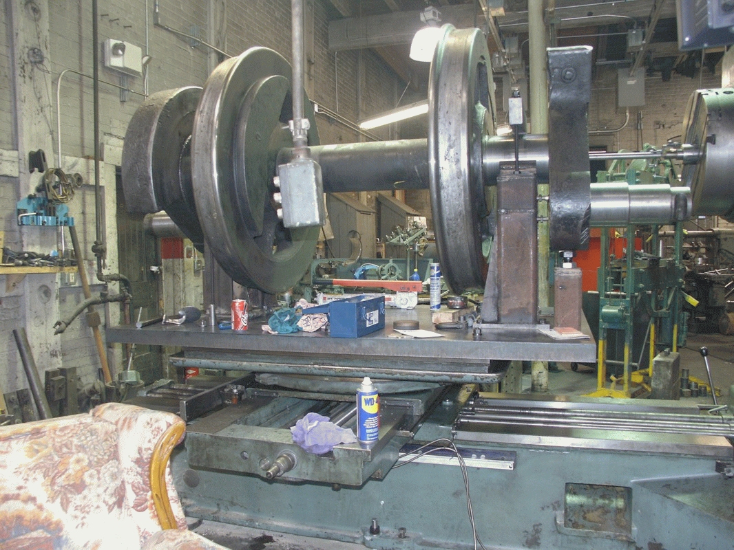
adammil1 wrote: Aarne H. Frobom wrote: On a side note how do the quartering machines work? Anyone have any good videos/pictures of the process? It would be neat to see. Adam, I ran a horizontal boring mill before and could suggest how I would do it using the set-up shown - but I don't know if the crank pin wear typically is so bad that no original machined crank pin diameter is available to indicate off of. Or, is the axle to crank pin distance known and you simply dial the x-axis over that distance and swing the crank pin up to the mill spindle and roughly indicate the pin in as best as possible? Either way, is the usual procedure to machine the crank pin under-size and then sleeve it back to original spec? Or are the crank pins removable? If I knew how these are assembled and what is the intended purpose (what needs fixing?) I could suggest possible ways of doing it. ![]() Steve |
Author: | machinehead61 [ Wed Dec 12, 2012 10:05 pm ] |
Post subject: | Re: Quartering Work. |
Searching this question I found a person that stated that the crank pins are machined undersize and then oversized bushings are used. The critical problem that I see is the side rod fit. If you have four driver wheels, then all four crank pins must be located within the tolerance of the bushing clearance. Assembling the first side of the locomotive is relatively straight forward. Each axle is free to rotate independent until it is in alignment for the side rod to fit the crank pins. The other side is where the quartering is critical since now the axles are rigid relative to each other due to the side rod on the other side. If you are off by .005" and your bushing clearance is .003", you won't be getting the side rod on. Plus, being off by a couple thousandths will put extra pressure on those bushings effected. The resulting heat could make the bushing fail. Steve |
Author: | JohnHillier [ Wed Dec 12, 2012 11:38 pm ] |
Post subject: | Re: Quartering Work. |
I'm curious about the picture of a set of K-36 drivers in that picture. It doesn't look like Durango, the ceiling is too cluttered. I'd also like to know how someone might quarter pins without a quartering machine. What about using a plumb-bob to find the crank pin center with your axle center? I've seen a couple shade tree ways of tramming engines, and I would imagine you could get pretty close to perfect using our imperfect human intuition. (I'd rather see it perfect and away from the shade tree, but sometimes...) |
Author: | Dave [ Thu Dec 13, 2012 12:38 am ] |
Post subject: | Re: Quartering Work. |
A couple observations: given the amount of play in the spring rigging as each axle independently moves up and down, a couple thousandths of clearance is far from enough no matter what the quartering. Grease clearance is the absolute minimum and will still probably run warm until it makes enough room on its own. Absolute quartering isn't required. Just make sure both sides are equally off. If you build a setup that gets the first wheelset an eighth inch out of quarter and use the same setup the same way and make all the others the same eighth inch off, she'll not know the difference. The problem is when they are each differently off. Indicate from the center of the crankpin and turn the OD with a portable crankpin lathe. Now you have something else to obsess about. Don't forget to also make sure the centers of the siderod bearings are also not only identical but correct, and the knuckle pins will screw you if you let them. That said, the tendency is to overthink and complicate what's a pretty straightforward job if you understand it correctly. If you don;t understand it, get somebody who does to come in and do it and teach it to you. dave |
Author: | Loco112 [ Thu Dec 13, 2012 1:27 am ] |
Post subject: | Re: Quartering Work. |
Crank pins are removable. If using a quartering machine, the pin would be pressed in to the wheel or counter balance (photo) and left oversized, to then be turned down to final with the quartering machine. With that method, even if the pin bore is not true, and the pin is pressed in and is extending out of its bore at a less than true position, the quartering machine will still cut the pin to the same axis as the main axle, (that the fixture is supporting) so the finnish cuts on the pin will be true even if the pins are pressed into holes that are not perfectly true. This is why the quartering machine is relied upon to take the fianal cut before the axles are put back in service. The photo above is the C&TS shop at Antonito, and the way they quarter is the only way to use the "big ol HBM method", like suggested above. I keep a photo of that setup for my future reference. A fixture (shown) holds the wheels solidly in thier correct postions. The HBM method (without using a driving wheel lathe with a quatering attachmnet), to turn driver center and or tires, is looked at as slightly "RR poor boy style", but it does work very well and is used very often now that few driving wheel lathes exist. You can use a large (huge) lathe (it can have a short bed in relation to its swing) and turn between centers to do the; wheels & journals, anything except the crank pin bores and quartering the pins. |
Author: | softwerkslex [ Thu Dec 13, 2012 1:51 pm ] |
Post subject: | Re: Quartering Work. |
If you can measure it, and bolt it down, anything is possible. I recall commenting a few years ago on this site on pictures of threads being "turned" on a large part by a cnc milling machine with a rotary profile cutter. Imagine the movements as the milling cutter is moved around the path of a thread profile. I can't recall if it was a multi axis head or if the table was doing the movement. |
Page 1 of 3 | All times are UTC - 5 hours [ DST ] |
Powered by phpBB © 2000, 2002, 2005, 2007 phpBB Group http://www.phpbb.com/ |