Railway Preservation News
https://www.rypn.org/forums/

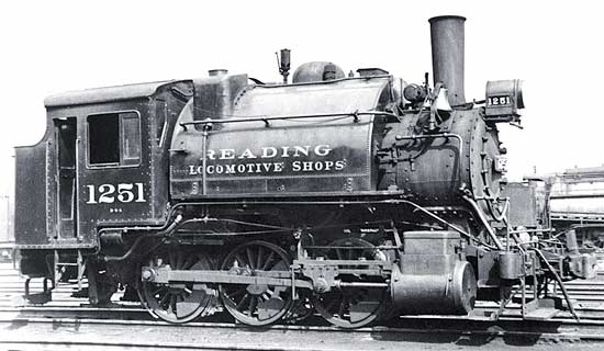
Need help understanding Steam Loco brake linkage (RDG#1251)
https://www.rypn.org/forums/viewtopic.php?f=1&t=34481
Page 1 of 1

Author:  Wowak [ Mon Feb 04, 2013 1:49 am ]
Post subject:  Need help understanding Steam Loco brake linkage (RDG#1251)

I suspect this is straying very close to the edge of acceptable topics here, and if it is deemed inappropriate I understand, but I'm going to go ahead.

I'm building a model of Reading's shop goat #1251 in O-scale (based on Lionel's 0-6-0 dockside switcher, but modified heavily.) I'm trying to model at least the highly visible components of the brake system. Unfortunately I'm not working from plans or blueprints, just whatever photos I have found from around the web. (Although I've seen 1251 in person at the RRMoP, it's not realistic to visit now for research from my home in Tennessee.) I can see the brake cylinder under the fireman's side, linked to the actuation lever, and I can see how it pivots to pull on the brakes on that side, and I can see from the (rarer, because of how she's displayed) pictures I have of the engineer's side that there is a matching lever on that side, but what I can't figure from these photos is by what manner of linkage the movement is transferred from the fireman's to the engineer's side.


Is anyone knowledgeable enough to elaborate? From what little research I've done, I've found that there seem to be many varied systems of rods, levers and pivots used in locomotive braking, none that I've seen seem to exactly match what I think I'm seeing under 1251.

For the curious, here's a photo of the work so far. It's not a bolt-counter's replica, more of an interpretation given the dimensions of the base engine (I've already had to remove the electronic whistle circuit and speaker to shorten the cab to an acceptable level.)

Image

Author:  Dave [ Mon Feb 04, 2013 10:09 am ]
Post subject:  Re: Need help understanding Steam Loco brake linkage (RDG#12

There's probably another brake cylinder under the engineer's side too.

dave

Author:  Chris Salmonson [ Mon Feb 04, 2013 7:31 pm ]
Post subject:  Re: Need help understanding Steam Loco brake linkage (RDG#12

Though not the brake linkage, but having to do with brakes, the air compressor is plumbed oppositely. The governor should lead to the steam jug (top) and the main reservoir should be connected to the air side (bottom)

Image

Reading Shop Switcher 1251

Looks like a really fun project!

Author:  J3a-614 [ Mon Feb 04, 2013 9:32 pm ]
Post subject:  Re: Need help understanding Steam Loco brake linkage (RDG#12

Here are a couple of photos of the 1251 from the right; as noted, there is a brake cylinder on the right, a mirror image of what is on the left. This is very typical of steam practice.

http://www.northeast.railfan.net/images/rdg1251s.jpg

http://www.readingrailroad.org/profiles ... 0_1251.jpg

The brake cylinders aren't normally connected across the locomotive directly; the connection is through the rest of the brake rigging, which incorporates a lot of equalizing levers in a series of links that connect all the brake beams together, connect both sides of the engine together, and do all this while allowing for slack and wear at various points. This is visible in this model part for an HO scale 0-8-0; the brake cylinders would connect on the two extensions at the left in the photo:

http://i.ebayimg.com/t/HO-SCALE-BRASS-B ... s2S5uJkBQo)OyCFO!~~60_35.JPG

Here is another model shot, in this case for a USRA light 2-8-2. In this case, as is typical of newer engines than the 1251, the brake cylinders are forward, behind the main cylinders and inside the frames, and the brakes apply from behind the axles. Brake hangers ard shoes are also on this model assembly, on the left side; they still need to be applied to the right side.

http://img156.imagevenue.com/img.php?im ... 176lo.jpg#

More model shots, in this case of a live-steam USRA 0-6-0; scroll down for the brake rigging photos.

http://www.friendsmodels.com/productsfo ... ge060.html

Hope this helps out.

Author:  Wowak [ Tue Feb 05, 2013 2:39 am ]
Post subject:  Re: Need help understanding Steam Loco brake linkage (RDG#12

Chris Salmonson wrote:
Though not the brake linkage, but having to do with brakes, the air compressor is plumbed oppositely. The governor should lead to the steam jug (top) and the main reservoir should be connected to the air side (bottom)

Good catch! I shall correct that.

J3a-614 wrote:
Here are a couple of photos of the 1251 from the right; as noted, there is a brake cylinder on the right, a mirror image of what is on the left. This is very typical of steam practice.

http://www.northeast.railfan.net/images/rdg1251s.jpg

http://www.readingrailroad.org/profiles ... 0_1251.jpg


I assume you're referring to the cylinder directly beneath the cab window. My concern with that is that it's NOT a mirror image of the fireman's side, where the brake cylinder is under the coal bunker and against the frame. So while I've put a cylinder in that location on my model, I can't see how it's connected to the brake lever (which is also visible, and IS a mirror image of the fireman's side.) That's why I assumed that wasn't the brake cylinder, but something else.

Author:  J3a-614 [ Tue Feb 05, 2013 3:40 am ]
Post subject:  Re: Need help understanding Steam Loco brake linkage (RDG#12

You're right; the brake cylinder itself isn't visible, but the lever leading to it is. That's what I was referring to, and perhaps should have been clearer about that.

The object you're looking at under the cab is an equalizing reservoir, another part of the air brake system. You may find this general schematic interesting--or at least I hope you do, as I dig stuff like this myself, especially in the form of the old technical manuals that turn up at a book shop now and then!

http://en.wikipedia.org/wiki/File:Westi ... iagram.jpg

http://en.wikipedia.org/wiki/Railway_air_brake

There are a couple of interesting things about this humble 0-6-0T. One is that it was a homebuilt job of the Reading shops, using parts from a 2-8-0. The other is that this locomotive ran well into the diesel age, not being retired until 1963! It would occasionally get into whistle salutes with Reading T-1 4-8-4s when the Rambles were running and showed up at the shops at 6th and Spring.

Equally amazing is that a Reading 0-4-0 Camelback survives, and it was in service during the Rambles era as well! It's at Strasburg, too!

Oh, and I'm a model enthusiast myself, of the Chesapeake & Ohio in HO. . .the REAL C&O, as David P. Morgan described it, in the era "before diesels and blue and yellow paint."

Have fun, just watch you don't go crazy with all the little stuff a steam model can have. . .:-D

Author:  Wowak [ Tue Feb 05, 2013 4:53 am ]
Post subject:  Re: Need help understanding Steam Loco brake linkage (RDG#12

I gotcha, and yeah, I can see the main lever, it just didn't make sense for it to be there unless there was a 2nd cylinder, or some mechanical linkage between them, and the cylinder is not visible in either of those pictures (which I did have among my collection.)

And yeah, I'm not sweating the details too much, the proportions aren't perfect and I'm not dead set on modelling every last detail, but trying to work it out brought out the curiosity in me.

Author:  G. W. Laepple [ Tue Feb 05, 2013 9:06 am ]
Post subject:  Re: Need help understanding Steam Loco brake linkage (RDG#12

After her career on the Reading was over, No. 1251 was purchased by the late George M. Hart. He moved her to York, Pa., where she was used for a time on his Rail Tours, Inc. trips on the Maryland & Pennsylvania. She was paired with a former Reading tender (converted to work train service) for water supply, and coal was heaped on top to refill the one-ton bins in each corner of the rear of the cab. The engine supplanted Canadian Pacific No. 1286 on short runs and made a few trips all the way to Delta, Pa. (33 miles each way) before CP ten-wheeler No. 972 was placed in service.

Author:  Lincoln Penn [ Tue Feb 05, 2013 1:37 pm ]
Post subject:  Re: Need help understanding Steam Loco brake linkage (RDG#12

Brian:

Your right side brake cylinder is in the shadows in these photos, under the very back of the cab and the coal bin.

Page 1 of 1 All times are UTC - 5 hours [ DST ]
Powered by phpBB © 2000, 2002, 2005, 2007 phpBB Group
http://www.phpbb.com/