It is currently Fri Aug 21, 2026 8:28 pm

All times are UTC - 5 hours [ DST ]


Post new topic Reply to topic  [ 35 posts ]  Go to page Previous  1, 2, 3  Next
Author Message
 Post subject: Re: CAD Modeling and simulating for steam
PostPosted: Tue May 12, 2015 3:37 pm 

Joined: Sun May 15, 2005 2:22 pm
Posts: 1543
I might have missed it, but does this group have all of the 2D drawings and specifications for building the original T1s? If not, what approach would be taken to complete the design for building a new locomotive?


Offline
 Profile  
 
 Post subject: Re: CAD Modeling and simulating for steam
PostPosted: Tue May 12, 2015 4:02 pm 

Joined: Tue Jul 17, 2012 5:24 pm
Posts: 79
I read that the group has over 300 of the original latest drawings out of 1200 total drawings. (number from memory) They go to PA archives a couple times a month to get drawings. They have everything below the boiler including the frame. Their CMO said they have 8 or 9 Mechanical Engineers from around the country converting the original drawings to Solidworks CAD. They hope to have complete running gear/frame/trailing and engine trucks completed by years end. This is all being done by volunteers and is a real grass roots effort. Pretty amazing.

From their Facebook Page today:

The T1 Trust is pleased to announce its first major corporate sponsor, Dassault Systèmes SolidWorks. In a deal worth over $20,000, Dassault has agreed to donate six SolidWorks network licenses to The T1 Trust.

Image


Offline
 Profile  
 
 Post subject: Re: CAD Modeling and simulating for steam
PostPosted: Tue May 12, 2015 4:44 pm 

Joined: Sat Feb 11, 2006 10:42 am
Posts: 335
Location: Wyoming, DE
Hello,

In my former life, corporately we went through an evaluation process between AutoCAD Inventor, Solidworks & Pro-Engineer to enter the 3-D world in design and manufacturing. I recall the best value and ease of use indicated Solidworks, mainly for PC based 3D CAD system. I believe Solidworks was started by ex Pro-E folks.

As the part count grows on this project so will the PC computing power.....at least a gaming level computer with a high end video card is a must.

At the start of my current job, my customer could not have realistically designed their engine compartments without 3-D.....if they had 2-D it would likely have had high rework. The envelope was too tight and had many parts to fit around the engines.

Solids software is matured technology now and can be used inside smaller organizations without breaking the bank.

Generating the T1 cylinders, ports and passages in 3-D opens the door for future CFD (Computational Fluid Dynamics) simulations.....analysis that Wardale could not do for the Red Devil Class 26 development in 1981...interesting possibilities. Perhaps this could be analogous the Duke of Gloucester.......on steroids.

Very impressive effort.

Regards,

Randy


Offline
 Profile  
 
 Post subject: Re: CAD Modeling and simulating for steam
PostPosted: Tue May 12, 2015 5:06 pm 

Joined: Tue May 21, 2013 3:20 pm
Posts: 89
Location: Vancouver Island
It's not in the US or Canada, but it is (was) a Baldwin, and is worth a look.

http://www.machineconcepts.co.uk/baldwin242/baldwin2.htm

I'm not a fan of ball valves for throttles, but that's another topic.

Pat


Offline
 Profile  
 
 Post subject: Re: CAD Modeling and simulating for steam
PostPosted: Tue May 12, 2015 5:18 pm 

Joined: Tue May 08, 2007 4:59 pm
Posts: 148
Quote:
Simulations are not bad, but the idea that you have to test everything might need to be balanced by "proven" designs. There were many T1's in operation.


The simulations play a very small role. The big bonus of working in 3D is finding errors in fit and tolerance. (clash detection) Though the simulations can help verify geometry etc.

When working from a existing set of drawings this becomes critical. Especially since you may be missing the latest revisions to a particular part. The 2D drawings that are created from the 3D models are not only critical to fabrication but are very important when it comes to checking the model against the historic drawings. Believe me... no matter how careful the CAD technicians are errors will creep in - especially when working of an old set of hand-drawn - 2D drawings that WILL have errors, conflicts and omissions galore! I am going through this now with the Stanley drawing!


Offline
 Profile  
 
 Post subject: Re: CAD Modeling and simulating for steam
PostPosted: Tue May 12, 2015 7:50 pm 

Joined: Sat Aug 21, 2004 10:52 pm
Posts: 914
Quote:
2D drawings that WILL have errors


Same with 3D drawings If you use 3D solids and fit them together, you stand a better chance of finding errors before manufacturing.

I recall one instance where we designed a parking lot for a building.

As usual (in Civil Engineering), we asked for an AS_BUILT so we could update our drawings and verify the actually built item would meet county standards. The site foreman said he'd built it EXACTLY to our plans.

When we got the as-built, we found he had an elevation error of about 3" in 150' (1 in 600) and it could cause drainage and flooding problems (according to county standards). Survey tolerances are typically 1:50,000.

All design work and building/manufacturing is about controlling errors. Manufacturing and design is the need to get a window of acceptable errors that will not hinder the final product from working.

A quick for instance it the railroad (chord) definition of degree-of-curvature (DoC) and highway (arc) DoC. I've seen museums worry this difference to death for months when the volunteers are not knowledgeable about errors.

1) railroad DoC is a larger radius than the highway DoC.

2) DoC highway is DoC = 5729.58 / R (5730 is typically accepted - off by 0.01%)

3) DoC railroad is DoC = 2 x sin(50 / R) (R = radius in feet).

4) In my book "Civil Engineering for Outdoor Railroads," I discussed error tolerance and the DoC. Synopsys:

If your error tolerance if 0.01% ( 1 in 10000), then either definition is good to a radius of 1500 feet (3.82 DoC). About 1.8"

If your error tolerance if 0.1% ( 1 in 1000), then either definition is good to a radius of just over 600 feet (9.55 DoC). Actual error is .11%. About 7.9"

If your error tolerance if 1% ( 1 in 100), then either definition is good to a radius of just over 200 feet (28.65 DoC). Actual error is 1.06%. About 2.12 feet or 25.5"

Choosing an error tolerance is paramount to any design and helps keep you focused on the important items.

Sorry this may sound like preaching but I doubt many understand this concept of error tolerance.

Doug vV


Offline
 Profile  
 
 Post subject: Re: CAD Modeling and simulating for steam
PostPosted: Wed May 13, 2015 12:02 am 

Joined: Sat Aug 31, 2013 4:11 pm
Posts: 287
I'll start by pleading simpleton. I'm not an engineer nor do a play one on TV. This thread along with some regarding best practices have been excellent.

The little bit of back and forth re simulation with regard to the T-1 CAD work to date may benefit from seeking a higher altitude. Remember that 2 goals are to increase lateral motion within its long wheelbase, and assess the suspension design to cut down on the front engine slip-i-ness. So that in mind, get the original engine frame and running gear into CAD then attack the design to handle these goals. Oh and at this point in time they are likely to have to design a "built up" frame v a cast one.

As for the broader question of the thread, I think we are witnessing the emergence of tremendous technical expansion in rail preservation. An expansion from loss prevention/preservation and operation, to preserving the design and engineering in a way that gives us a virtual look into the total machine from idea to reality.


Offline
 Profile  
 
 Post subject: Re: CAD Modeling and simulating for steam
PostPosted: Wed May 13, 2015 8:23 am 

Joined: Sun May 15, 2005 2:22 pm
Posts: 1543
Is it expected that the group will acquire all of the original drawings by some point, or will of some of them remain unavailable? If say 15% of the drawings will not be available, what will they do to overcome the problem of the missing information?


Offline
 Profile  
 
 Post subject: Re: CAD Modeling and simulating for steam
PostPosted: Wed May 13, 2015 8:33 am 

Joined: Sun Aug 22, 2004 7:58 am
Posts: 728
Quote:
Is it expected that the group will acquire all of the original drawings by some point, or will of some of them remain unavailable? If say 15% of the drawings will not be available, what will they do to overcome the problem of the missing information?


Research on PRR (and general steam locomotive) practices of the time, followed up with a good dose of engineering.

Steve Hunter


Offline
 Profile  
 
 Post subject: Re: CAD Modeling and simulating for steam
PostPosted: Wed May 13, 2015 10:19 am 

Joined: Sun May 15, 2005 2:22 pm
Posts: 1543
This is where it appears to me as a very difficult needle to thread. Parts lacking drawing documentation will have to be redesigned as entirely new parts including concept, shape, material, and engineering, and also the context of their relationship to other parts that may lack documentation. It seems to me that it would be very difficult to split the purpose between reproduction of the historical locomotive and a modern-day design effort of new portions of the locomotive.

In fact that issue may emerge even where all the part drawings are available, as the prospect of improving the original, known design looms ever present; and considering that the locomotive may have had some design issues that have been recognized as needing improvement for functionality.

My main point is that redesign of a locomotive is a many times larger effort than reproduction of an existing design. I speculate that the cost of all this engineering and design work may rival the actual cost of construction.


Offline
 Profile  
 
 Post subject: Re: CAD Modeling and simulating for steam
PostPosted: Wed May 13, 2015 10:58 am 

Joined: Tue Jul 17, 2012 5:24 pm
Posts: 79
The T1 group has said they have located nearly every major component. The ones they are not having much luck with "off-the-shelf" components the railroad would have just purchased. Those detailed drawings don't exist, but there are plenty of those components out there (like Air Compressors) to purchase or make.

You can do what I did and join the group (its free) and read their member forum. Lots of details and discussions about how to approach everything. Lots of great minds. A lot has gone on that most people have no idea.

Every month they go to the archives and buy more drawings to convert. I have made several donations to the effort. If you find this interesting, I would suggest you sponsor one of these drawings. They have some for $20. This is the only way it will get done. I hope to sponsor a couple more yet this year. I know it seems like a pipe dream, but it seems they are getting a little closer to reality.

Check out their fundraising center - http://prrt1steamlocomotivetrust.org/


Offline
 Profile  
 
 Post subject: Re: CAD Modeling and simulating for steam
PostPosted: Sat May 16, 2015 9:51 am 

Joined: Mon Nov 26, 2007 2:54 am
Posts: 1078
Location: Califoothills / Midwest Prairies / PNW
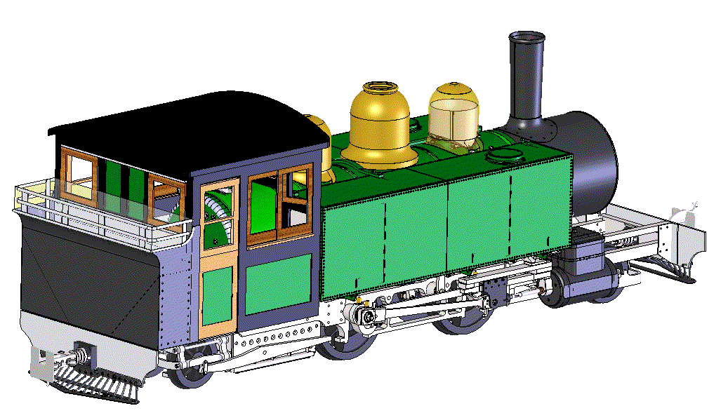
In the U.K. CAD modeling has been used for half a decade in the production of the new locomotive recreation "Lyn". They are rather far along in the casting and machining of parts for this new 2' gauge Baldwin.
http://www.machineconcepts.co.uk/baldwin242/baldwin.htm
Image


Offline
 Profile  
 
 Post subject: Re: CAD Modeling and simulating for steam
PostPosted: Sun May 17, 2015 5:31 pm 

Joined: Tue Jun 26, 2007 12:00 am
Posts: 554
Location: Dallas ,Texas. USA
ted101 wrote:
The T1 group has said they have located nearly every major component. The ones they are not having much luck with "off-the-shelf" components the railroad would have just purchased. Those detailed drawings don't exist, but there are plenty of those components out there (like Air Compressors) to purchase or make.

Check out their fundraising center - http://prrt1steamlocomotivetrust.org/


I would be very interested in seeing what appliance and appurtenance "PARTS" drawings the T1 group found and what they still need.

I've been begging the entire rail fan community, and specifically everyone with a accurate replica project to help locate those after market (appliance / appurtenance) drawing sets and get them from the original steam era manufacturers while they are still not trashed. Remember ALCO! The person who has such a set can then trade them for any other set, that ohter guys have, and that encourages others to get to work to find other sets. The idea is that one person should only need to take the time, effort and expense, to find one grand set and then he could trade that set to others. Eventually everything would get found and scanned and everyone would have traded and swaped and all those sets untill everyone that wnated a set had that set, and eventually a copy set would get to each of large RR archives.

Its been 20+ years that I have worked on that idea and i can count the guys that do that research and trading on one hand. I call the replica guys that actually collect and use detailed drawings and accurate info Replica "projecteers" (sort of like Mouseketeers, but for trains) and I've also encourage every one I've ever spoken to to use any type of CAD program to assemble their data so that specific project only has to be labored on one time, not over and over and over.

The only group that has a hope of actually searching out and working, and as a bye product, preserving all the steam era appliance / appurtenance drawing sets are the Live-steamers. They are the only group with an incentive to go through all that expense and effort, and only the "rivet counters" within that group want every drawing. Typical live steamers have the same info requirements that the RR-Simulation guys have, they just want the erecting drawing with the few cross sections and they guesstimate every other dimension. Neither the typical Livesteamer nor the RR-Simulation guys, can justify lengthening their project timelines 20 to 40 times (longer) to do an accurate detailed CAD project when they can get by with just a single Erecting drawing.

A real replica reconstruction project needs everything they can get, and that's typically 400-2000 huge original detailed drawings just for the locomotive. The appliances and appurtenances can also have 400 drawings.

Anyone who wants to help preserve a set of appliance / appurtenance blueprints, as used by replica projects like the T1 group, just contact me and I'll get you started. Time is running out.

Post what that the T1 group has and needs and I'll try to help.

_________________
Loco112 (NarrowGaugeExchange Forum)

Our "paper" archives will be the future railfans only hope. We (yes you too!) should endeavor to preserve all the info needed to allow them 100% accuracy in the building of their recreations.


Offline
 Profile  
 
 Post subject: Re: CAD Modeling and simulating for steam
PostPosted: Mon May 18, 2015 2:15 pm 

Joined: Sat Aug 21, 2004 10:52 pm
Posts: 914
Hi,

Comment to monitors.

The subject here "CAD Modeling and simulating for steam" in the BOLD and squared off lettering used on the board is funny. Every time I see is I Read "C&O Modeling and simulating for steam."

If I'm the only one with this problem, please feel free to erase this post.

Doug vV


Offline
 Profile  
 
 Post subject: Re: CAD Modeling and simulating for steam
PostPosted: Mon May 18, 2015 2:50 pm 

Joined: Tue Sep 14, 2004 7:52 am
Posts: 2477
.


Last edited by Kelly Anderson on Thu Aug 08, 2024 11:03 pm, edited 1 time in total.

Offline
 Profile  
 
Display posts from previous:  Sort by  
Post new topic Reply to topic  [ 35 posts ]  Go to page Previous  1, 2, 3  Next

All times are UTC - 5 hours [ DST ]


You cannot post new topics in this forum
You cannot reply to topics in this forum
You cannot edit your posts in this forum
You cannot delete your posts in this forum
You cannot post attachments in this forum

Search for:
Jump to: